
![]() Ornithopter Flight Dynamics and Control
Ornithopter Flight Dynamics and Control
Executive Summary
As new mission profiles require smaller vehicles, flapping-wing ornithopters
become increasingly attractive as an alternative to conventional fixed-wing and rotary-wing aircraft.
This work looks at creating dynamical models of flapping-wing flight dynamics which can be used in
conjunction with tailored control algorithms to improve elements of the flight performance, and also
to exploit the agility and maneuverability of flapping-wing flight.
Primary Project Objectives
- To accurately model the flight dynamics of an ornithopter
- To develop control algorithms which both improve and exploit the unique flight dynamics exhibited by flapping-wing aircraft
- To construct avionics hardware and perform mission scenarios autonomously
Detailed Research Description
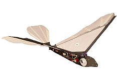
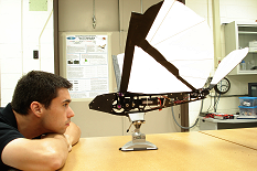
The goal of this research is to understand and manipulate the flight dynamics of flapping-wing vehicles so that they can fill a niche in the MAV world, left disjoint by the capabilities of conventional fixed-wing and rotary-wing aircraft. The main test bed vehicle for this work is shown below. The stock ornithopter weighs about 450 grams and has a 4 ft wingspan. Flight times can extend up to 30 minutes.
 |
 |
Odyssey |
Jared with Odyssey |
Double-click the below movie taken of one of our flights to see what ornithoptic flight looks like:
|
QuickTime Format. or try a different browser. Quicktime Player required for viewing. You can download a free player HERE |
|
The first question to answer is can the standard aircraft model used with conventional fixed-wing and rotary-wing aircraft be used to model an ornithopter. The standard model consists of the rigid body equations of motion for a single body, which may be augmented to describe additional subsystems such as actuator motions or rotor dynamics. These models are well suited to larger conventional aircraft, and also to smaller biological flight vehicles such as insects. However, this research group is finding that for ornithopters large enough to carry the required avionics payload, the mass distribution undergoes large changes with the wing stroke and the relative motions of the wing generate significant forces which are not captured by a single body model. For instance, the figures below illustrate the migration of the center of mass and of the components of the inertia tensor over the course of a wing stroke.
Double-click the below movie to see the center of mass position and the inertia ellipsoid changing in time as a function of the wing angle:
|
QuickTime Format. or try a different browser. Quicktime Player required for viewing. You can download a free player HERE |
|
The left side shows the ornithopter geometry and the center of mass as a green sphere. The right side shows the inertia ellipsoid, which is found by taking the eigenvalues and eigenvectors of the inertia tensor.
 |
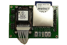 |
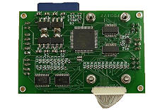
avionics board |
avionics board |
Another question to answer is what do the dynamics of an ornithopter actually look like, and how do we observe them. Typically with unmanned air vehicles GPS can be used to measure position, while inertial measurement units can be used to provide information about orientation and velocities. A custom avionics board was created, (shown above). The board consists of an 8-bit microprocessor running at 40 MHz, which samples data and logs it to a removable memory card. Measurements from triads of MEMS magnetometers, gyroscopes, and accelerometers are time stamped at 250 Hz, as well as the control inputs sent to the ornithopter and the corresponding actuator responses.
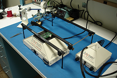 The avionics are prototyped and then designed in house, commercially manufactured, and then manually populated with our reflow soldering equipment, shown left. Measurements were taken onboard the ornithopter about straight and level mean flight.
The figure below shows ensemble averages of the measurement signals
The figure below shows the Fourier transforms of the signals.
This work quantitatively shows that the ornithopter experiences violent pitching and heaving motions in the most benign flight condition of straight and level flight. The structural modes seen in the frequency domain data hint that the current design should be strengthened to eliminate bending and torsion modes in the airframe. Additionally the large accelerations experienced and the poor quality of gyroscope measurements prohibit conventional attitude estimation techniques used by fixed-wing and rotary-wing aircraft and requires a model-based state estimator.
 A model of the flight dynamics is required to progress further. To capture the changing mass distribution and to account for all the variables needed to incorporate gravitational, centripetal, Coriolis, and aerodynamic forces on the ornithopter, a multibody model is constructed, shown left. The model consists of a base body for which we can express the generalized position and velocity variables. There are additional appendages stemming from the base body, representing the wings and the tail mechanism. Generating the equations of motion for a system such as this is commonplace in the spacecraft and robotics literature, and the Lagrangian formulation easily lends itself to nonlinear control design and adaptive system identification techniques. Using this framework, control algorithms and state estimation techniques will be implemented in hardware and used to make the ornithopter fully autonomous.
![]()