
![]() Aerodynamic Modeling of a Flapping Membrane Wing using
Aerodynamic Modeling of a Flapping Membrane Wing using
Motion Tracking Experiments
Executive Summary
The ornithopters used by Team Morpheus experience dramatic shape change of the flapping membrane wing throughout a complete flapping cycle which make it challenging to model aerodynamically. To solve this problem a Vicon motion tracking system was used to quantize the wing shape throughout a flapping cycle while lift and thrust were measured using a strain gauge transducer. Using the shape data, a blade element approximation of the wing was established with accurate descriptions of the local stroke angle, pitch, flapping velocity and membrane shape along the wing span. Both membrane aerodynamics and unsteady aerodynamic theory were applied to generate a predictive aerodynamic model that could be compared with measured lift and thrust data. Current results show good correlation between the model and measurements, and the research is being finalized into a Masters Thesis document.
Primary Project Objectives
- Quantize the ornithopter dynamic wing shape over a flapping cycle
- Develop a geometric blade element model of the wing
- Determine local wing pitch and bending angles, velocities and accelerations
- Apply aerodynamic theory to calculate aerodynamic forces versus stroke angle
- Compare aerodynamic model results with measured aerodynamic forces
- Suggest improvements to ornithopter design
Research Description
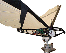
To date, there are no known studies that track a membrane wing’s shape and motion in three-dimensional space and use the experimental information for aerodynamic analysis. In order to complete this research two ornithopters from the University of Maryland’s Morpheus Laboratory were selected for analysis, they are Odyssey (white wings) and Trinity (blue wings).
 |
 |
Odyssey |
Trinity |
When operating at steady level flight conditions the ornithopters flap their wings three to six times per second and can reach speeds of thirty kilometers per hour. Their wings are composed of ripstop nylon stretched over a network of carbon fiber spars and fingers. There are two spars, one at the leading edge and another placed diagonally from the leading edge to the rear of the fuselage. The fingers link the diagonal spar to the trailing edge to provide support to the rear “flap” area of the wing. During flight the flapping wing undergoes dramatic twisting and bending as a reaction to the acceleration and aerodynamic forces the membrane experiences. High speed photographs of the wing stroke were formulated into a video to show this phenomenon.
|
QuickTime Format. or try a different browser. Quicktime Player required for viewing. You can download a free player HERE |
|
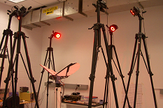
 To form an accurate aerodynamic model, the wing dynamics
needed to be measured and the behavior of the wing characterized. The
Autonomous Vehicle Laboratory at the University of Maryland
offered the use of a Vicon motion tracking system which identifies reflective markers
placed on the wing and provides 3D tracking data of those markers after post processing. Both
ornithopters were outfitted with about 100 markers on their left wing and tracking data was recorded
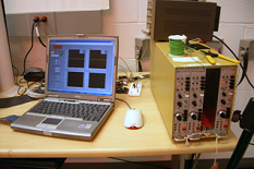
for a variety of flapping frequencies. During these experiments, the ornithopters were mounted to a
rigid test stand via a strain gauge transducer which measured the lift and thrust forces produced during
the experiments. Photos summarizing the experiment are given below, along with a sample of the post
processing results in the form of a wing tracking video.
To form an accurate aerodynamic model, the wing dynamics
needed to be measured and the behavior of the wing characterized. The
Autonomous Vehicle Laboratory at the University of Maryland
offered the use of a Vicon motion tracking system which identifies reflective markers
placed on the wing and provides 3D tracking data of those markers after post processing. Both
ornithopters were outfitted with about 100 markers on their left wing and tracking data was recorded
for a variety of flapping frequencies. During these experiments, the ornithopters were mounted to a
rigid test stand via a strain gauge transducer which measured the lift and thrust forces produced during
the experiments. Photos summarizing the experiment are given below, along with a sample of the post
processing results in the form of a wing tracking video.
 |
 |
Odyssey with cameras |
Trinity Test Stand |
 |
|
Trinity force transducer |
Laptop |
|
QuickTime Format. or try a different browser. Quicktime Player required for viewing. You can download a free player HERE |
|
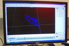
 Using the locations of the reflective markers, the wings
were broken down into a dozen blade elements to be analyzed individually based on the 3D tracking
data. A MATLAB program was written to take in wing tracking and load measurement data, wing geometry,
and the forward velocity condition. The blade elements were formed inside the program and local pitch
and stroke angles were calculated, as well as the blade’s velocity and acceleration which factor
into the relative velocity and apparent mass forces. Unsteady aerodynamics and membrane aerodynamic
theories were applied to produce a model of the aerodynamic performance at that forward velocity
condition. Results are compared to the measured lift and thrust and discrepancies are studied. A
sample result from the aerodynamic modeling code is pictured below, with calculated and measured values
compared and the stroke position provided as a reference.
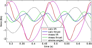
Using the locations of the reflective markers, the wings
were broken down into a dozen blade elements to be analyzed individually based on the 3D tracking
data. A MATLAB program was written to take in wing tracking and load measurement data, wing geometry,
and the forward velocity condition. The blade elements were formed inside the program and local pitch
and stroke angles were calculated, as well as the blade’s velocity and acceleration which factor
into the relative velocity and apparent mass forces. Unsteady aerodynamics and membrane aerodynamic
theories were applied to produce a model of the aerodynamic performance at that forward velocity
condition. Results are compared to the measured lift and thrust and discrepancies are studied. A
sample result from the aerodynamic modeling code is pictured below, with calculated and measured values
compared and the stroke position provided as a reference.
![]()